Recently, due to increasing demand for high data rates using mobile networks, there have been huge efforts to increase the number of antennas in cellular communication systems. Conventional MIMO RF transmission systems consist of digital-to-analog converts (DACs), mixers, oscillators, and antennas, and the number of RF systems increases proportionally as the number of antennas increases. Specifically, a massive MIMO system, where using more than 100 antennas is suggested, requires an equal number of RF systems, which leads to significant power and complexity issues.
In order to solve the aforementioned issues, various approaches to implement the single RF concept have been proposed. However, an actual system design with experimental results has not been reported yet.
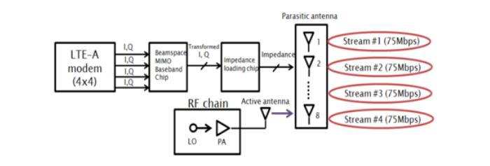
Figure 1 depicts the proposed single RF transmission system. It consists of a carrier source, impedance loading boards, and antennas. The carrier signal generated from the carrier source first goes to the impedance loading board. The impedance loading board loads the impedance between the carrier source and the antenna, and it controls the current flowing through each antenna, finally leading to the change of radiation pattern that the antennas emit. In a multi-stream system, every antenna and RF system shares one carrier source, which is a power amplifier (PA). By sharing the power amplifier and using only passive components (R,L, and C) in the impedance loading board, the proposed system has a big advantage, not only in terms of the overall system complexity but also the power efficiency.
In the system, the two main components are the impedance loading board and the antenna. The impedance loading board should be able to switch the impedance value between the carrier source and the antenna at a high speed (every ~30 ns). Also, the antenna must be small enough to be used in a small base station.
 Antenna for a single RF system
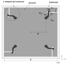
The structure of the antenna is described in Figure 2. The antenna is composed of four antenna elements which are based on the L-shaped slot antenna structure. The antenna is made of Taconic RF-60a substrate with a thickness of 0.79mm( ). The total size of the antenna is 80mm x 80mm and the antenna’s resonance frequency is 2.375GHz. Antennas are fed by a coaxial cable connected to the bottom ground of the antenna.
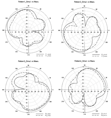 The antenna is modeled using a commercial EM full-wave simulator: CST 2011 software. The simulated and measured radiation patterns in the azimuth plane of the antenna are presented in the figures below. Each antenna radiates in different directions for low correlation with other antennas. The antenna gain is 4dBi in the main-lobe direction.
The correlation coefficient calculated at the farfield pattern is important to single RF systems. For all radiation patterns, the calculated correlation coefficients of the proposed antenna are less than 5%.
Impedance loading board for single RF systems
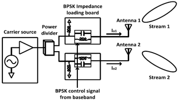 Right figure depicts a two-stream BPSK-based single RF transmission system. This system consists of a carrier source, impedance loading boards, and antennas.
The baseband decides the impedance value, and the impedance loading board changes its impedance using switches. For example, in BPSK impedance loading boards, there are two states, state 0 and state 1, which are the same in magnitude and have a 180-degree difference in phase. The impedance loading board consists of switches and passive lossless elements. As shown in below figure, the switch control signal from the baseband decides whether the impedance path is inductive or capacitive. Because this impedance loading board uses passive lossless elements, power is only consumed by the switches. Each impedance loading board uses a 2.5V power supply and consumes 3mA at a 20MHz chip rate.
In summary, the proposed single RF concept is a promising technique for several reasons: (1) all RF systems share only one PA, which creates a sizable advantage in terms of PAPR; (2) a RF system is a much simpler than that of a conventional MIMO, especially when a massive number of antennas is used.


